Automatic Pool Cover Key Switch Wiring Diagram
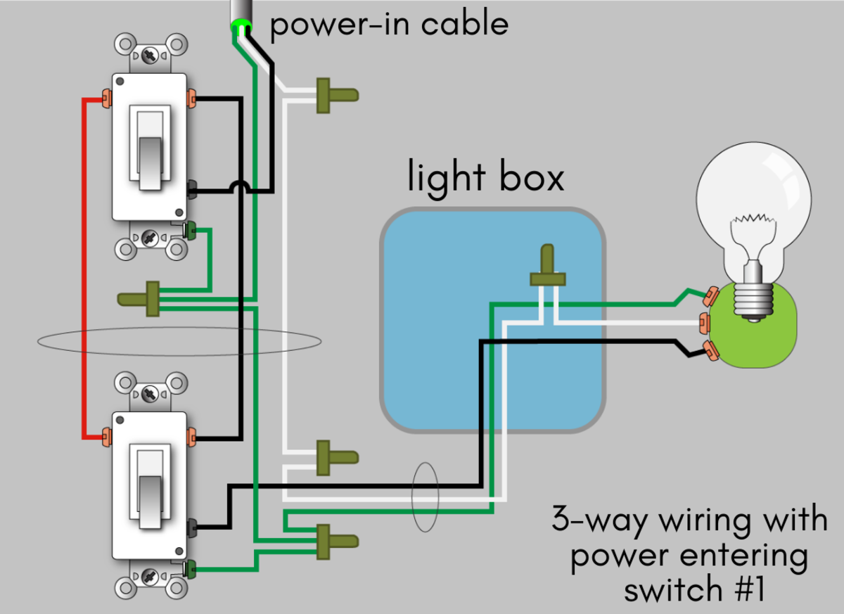
Electrial wiring diagram and details and shown below. It shows the components of the circuit as simplified forms as well as the power and signal connections in between the gadgets.
Navigation Lights Wiring Diagram Hazard Lights Navigation Lights Diagram

I have a Red wire to one terminal and a black to the other.

Automatic pool cover key switch wiring diagram. A flashing green light means the cover. It has been used use for 15 years. This Pool Cover Specialist PCS Low Voltage Key Switch is the most standard key switch they have.
This easy-to-use touchpad also. The CoverLink digital control allows you to program four access codes for access to the pool cover system. Remove the control key from the key switch and store it in a secure location to prevent unauthorized operation of the.
I took the motor and switch assembly which includes this pool saver limiter to the electric repair shop. Detach the key switch box from the existing flex conduit and attach it at the new location. Low Voltage Key Switch.
Wire from the power supply the white wire from the motor and one of the wires from the indicator light together using a wire nut. Doing so can irreversibly damage controller and cover motor and potentially cause serious injury or death. Automatic Pool Cover Owners Manual.
Damaged Touch Pad or key switch To test bypass the key switch or touch pad by isolating the motor control wires small gray. Work with a system that has redefined the standards of quality and design. Wiring The Electrical Switch The control switch mush be mounted in an all weather box in a location where 100 of the pool is visible.
Wiring Diagram Mio Sporty Archives Joescablecar 2018 Wiring. All switches must be. Switch is to be remotely located the pool cover must be completely visible at all times.
Then I have a green wire. Automatic Pool Covers APC OEM Part EC0369. A wiring diagram is a simplified traditional photographic representation of an electrical circuit.
Try operat-ing the cover again. It also has a very user-friendly lighting system. Two 38 hoses up to 80 runs HYDRAULIC POWER PACK 3 high-voltage wires 12 AWG under 50 3 high-voltage wires power.
Ok I just got my pool cover motor rebuilt for 270 and then took it back home and installed it to realize it didnt work. Variety of automatic pool cover wiring diagram. A wiring diagram usually gives info concerning the family member placement.
Un-plug and then remove the pool cover pump from the pool cover and the recreational area before operating the pool cover or swimming in the pool. Pool Cover Specialist PCS. - Press button 2 to confirm the closed position.
Pool Cover Specialist PCS OEM Part IN1104. IDEC keyswitch Assembly - low and high voltage. They said they could bypass it by wiring in a 120V key switch at 280 which would take them one hour.
Red blue power black to switch key switch KOSA ELECTRICAL Choose electric or hydraulic power and controlling devices. POOL COVER HOUSING Conduit with 3 18 AWG Identified Wires for Low Voltage Key Switch Option 1. I have a pool cover switch that will open the cover but wont close.
Apr 9 2010. POOL cover housing All switches must be mounted in full view of the cover operation. Simply turn the key to cover or uncover the pool.
Continue to pull the cover over the pool and RELEASE THE KEY when the cover is fully closed the auto stop is not activated yet. Wiring Diagram Motor Control System Best Remote Controllable. Then wire the motor and key switch as explained in the wiring diagram.
8-pin Wiring Harness for Key Switch. I laughed knowing anything pool related is 20X the price of the normal part. - Using the key switch roll the cover out fully over the pool stop it when the leading slat touches the wall opposite the axle.
Automatic Pool Covers APC OEM Part EC0226. Low Voltage Key Switch. Touch the brown wire to the green wire and then flip the power breaker off for ten sec-onds.
Reset the power breaker and again touch the brown wire to the green wire. Other side of switch has a greentan jumper wire between the two terminals. Run a pig tail from this wire nut to the grounding lug on the switch.
- Roll the cover up fully stop it when the leading slat is 10cm below the water level. Pool Cover manufacturers in the US actually sell wireless touchpads to go with their covers. 2009 Touch-Sensitive Touchpad Assembly Without Box.
Attached is a wiring diagram for what I currently have and an additional diagram of bypassing the limiter by installing a 120V key switch. Variety of automatic pool cover wiring diagram. Our structures boast a simple mechanical system premium treatments and coatings and industrial grade parts that are built to last.
Pool Cover Specialist Low Voltage Key Switch. Operating the pool cover Based on your choice of accessories your pool cover will be controlled by either a Key Switch or a Touch Pad mounted in full view of the pool. Switch must be mounted in a position with a full view of the pool.
The key switch control comes standard with automatic cover systems with Auto Shutoff. A green light on the unit means the system has power. Investing in an automatic pool cover.
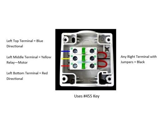
Pull 4 x 14 gauge different colored wires red blue yellow black through the conduit. - Includes Key Part 11722 - Includes Switch Face Plate - Box Not Included. I believe they are far safer than key ignition when used properly because pool owners almost always just leave the keys in the switch.
Key Switch Touch Pad. Click on the image to enlarge and then save it to your computer by right clicking on the image. Turn the key to feed the ropes onto the rope reels.
SYSTEM LAYOUT WHrrEN1 12 WIRE 2. They just need to be mounted in view of the pool. Key Switch 5v Conduit for Main Power with 3 14 AWG Identified Wires Hot Neutral Ground Conduit with 4 14 AWG Wires For Power and 3 18 Awg for Sensors Conduit with 4 18 AWG Wires J-box 8 Bonding Wire Both Ends Conduit with 4 18 AWG min.
Automatic Pool Covers Inc. Run an extra conduit from the equipment pad to the remote location. A wireless option allows for passcodes alarms and alerts.
So Here I am searching for ideas maybe hoping someone with experience with electronics and or Pool Saver could help. This key switch control comes standard with the PCS automatic cover systems. It is a solid state switch with 4 terminals.
User manual installation owners wiring instructions 110vac 3 wire electric cover modpools remote controllable automatic pool motor diagram ac gearmotor help diy home neo by eca shutter ellis covers inc durable and parts auto bypassing abs pump full pools 50134 model save t ii aquamatic key switch box with legend guide infinity 4000 hydraulic 2 way to electrical 32 siemens. Make sure the cover sides ARE ALIGNED STRAIGHT to feed directly into the track. The automatic cover system must be bonded to meet the National Electrical Code.
AUTOMATIC NEW ENGLAND WARNING POWERTOUCH WIRING Electrical Wiring Diagram A WARNING A Do not attempt to connect or disconnect the control unit or motor harness while supply power is ON. Home Coverstar Leviton Key Switch Assembly Complete with Light STD A0605. The Texas weather emergency in February in addition to the ongoing demand increase for pool products from the Covid pandemic have caused industry-wide shortages on many products that most vendors expect to last late into 2021early 2022.
The LED will continue to blink. Simply turn the key to cover or uncover the pool. 800210 REL-0001 4 of 23 PROTECT YOUR INVESTMENT Your automatic cover is designed to perform reliably.
Connect the ground wires from the power supply and the motor together using a wire nut. This key switch uses APCs SmartStop single sensor auto-stop to prevent the pool cover from opening or closing too far. With the AutoGuard system youll get 365 days of the safety you need and the convenience you want.
Diagram Ignition Light Wiring Diagram Full Version Hd Quality Wiring Diagram Soadiagram Prcsestosg It

4 Wire Ignition Switch Diagram Atv New Excellent Chinese Cdi Wiring Best Of Kill Switch Motorcycle Wiring Electrical Diagram

Diagram Wiring Diagram Three Way Switch Hansenf Theboringcompany It
Blue Sea Acr Wiring Diagram Electrical Circuit Sure Power Battery Home Electrical Wiring Boat Wiring Distribution House

Diagram Suzuki Drz125 Wiring Diagram Breathan Theboringcompany It

Diagram Light Switch With Schematic Wiring Diagram Backcot Medievalarte It
Diagram Simple Light Switch Wiring Diagram Grinbis Antonellapetragallo It
Diagram Wh40 Wiring Diagram Cadta Stilechetogenico It

Diagram Cover Star Pool Cover Wiring Diagram Basklanp Trasportopiu It
Davey D40va Automatic Sump Pump 02 Gfci Electrical Panel Wiring Hot Tub Delivery

Wire A Bilge Pump Switch Boat Wiring Boat Battery Pumps

6 Terminal Toggle Diagram In 2021 Toggle Switch Electronic Schematics Basic Electrical Wiring

Diagram Tarp Rocker Switch Wiring Diagram Full Version Hd Quality Wiring Diagram Soadiagram Prcsestosg It

Wire Harness Wiring Cdi Assembly For 50 70 90 110cc 125cc Atv Quad Coolster Go Kart Wish Motorcycle Wiring Chinese Scooters 90cc Atv

Blue Sea Battery Switch Wiring Diagram Boat Wiring Diagram Wire

Diagram Pool Pump Switch Wiring Diagram Full Version Hd Quality Wiring Diagram Soadiagram Prcsestosg It

How To Wire A Float Switch Tameson Com

Electronic Circuit Breaker Schematic Diagram Electronics Circuit Electrical Wiring Diagram Simple Electronic Circuits

Digital Pool Heater Troubleshooting Guide Electrical Wiring Diagram Pool Electrical Swimming Pool Electrical


Posting Komentar untuk "Automatic Pool Cover Key Switch Wiring Diagram"