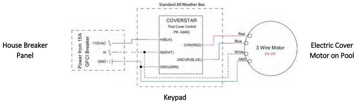
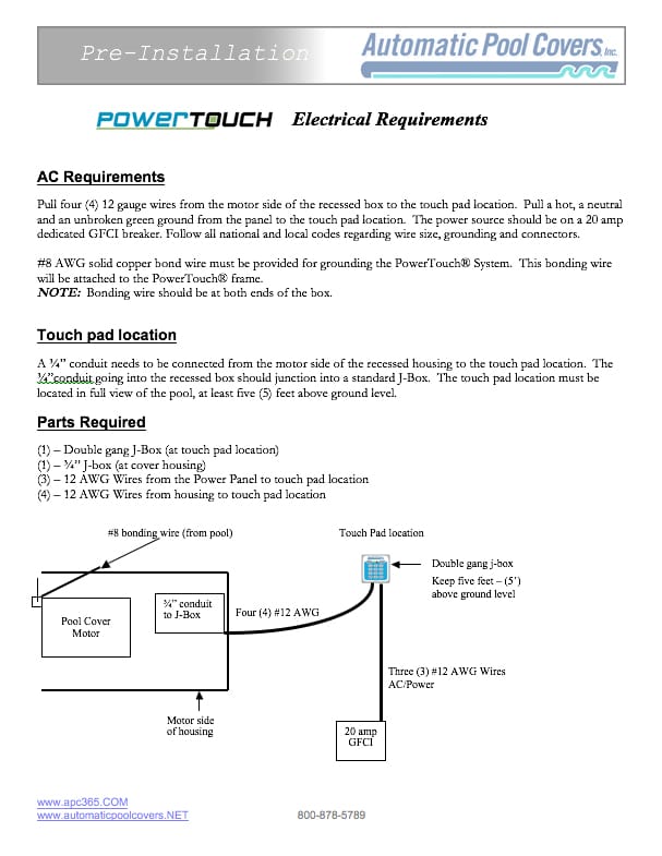
Pool Cover Motor Wiring Diagram
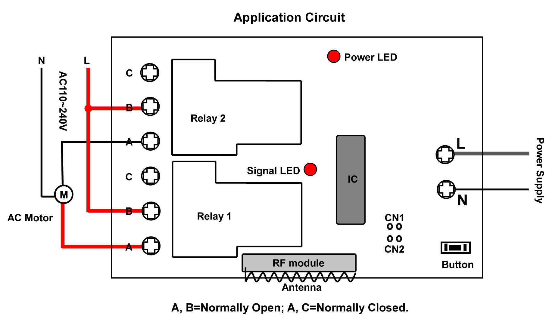
Cover housing POOL POWE R SOURCE ¾ hp motor 15 amp 1½ hp motor 20 amp. Automatic pool cover wiring diagram Wiring Diagram Motor Control System Best Remote Controllable Automatic Pool Cover by High Power Remote.
2
Maximum flexible cord length for pump is 3 Ft.
Pool cover motor wiring diagram. If a pump motor receptacle is located between 6 10 from the inside pool wall the receptacle must be a single twist-lock outlet grounded and GFCI protected. Anchoring the mechanism 914 Wiring the electrical switch. Key Switch 5v Conduit for Main Power with 3 14 AWG Identified Wires Hot Neutral Ground Conduit with 4 14 AWG Wires For Power and 3 18 Awg for Sensors.
Attaching the roll-up tube 82. By Admin December 3 2017. Aquamatic Pool Cover Wiring Diagram wiring diagram is a simplified usual pictorial representation of an electrical circuit.
Variety of infinity 4000 pool cover wiring diagram. Swimming Pool Timer Wiring Diagram For Spa Pump Wiring Diagram New. Reversible means that the pump motor can accept either V or V.
12 AWG over 50 ft. Main circuit breaker panel Dedicated 120VAC20 amp. I took the motor and switch assembly which includes this pool saver limiter to the electric repair shop.
Click on the image to enlarge and then save it to your computer by right clicking on the image. The industry-standard for rope automatic pool cover systems the Save-T 3 big RED is built from stainless-steel and anodized aluminum and uses an advanced 34 horsepower high-torque waterproof motor. SYSTEM LAYOUT WHrrEN1 12 WIRE 2.
Then wire the motor and key switch as explained in the wiring diagram. If the mechanism housing has been flooded or any of the electrical connections have been compromised ie. 84 Extending the Pulley brackets 85.
A wiring diagram normally provides information regarding the relative position and also plan of gadgets. 84mm solid copper conductor between this unit and the bonding grid and is require by code. AutoSave The AutoSave spa and swim spa cover offers the same safety and energy-saving benefits as a full-size automatic pool cover but with a more.
Ok I just got my pool cover motor rebuilt for 270 and then took it back home and installed it to realize it didnt work. Assortment of automatic pool cover wiring diagram. Try to run the motor by touching the red wire to the green and then the black wire to the.
Each component should be set and connected with different parts in particular way. If Auto-shutoff is located in the cover housing use two conduits 1 high voltage and 1 low voltage AUTO SHUTOFF W AMP LIMITE R ACC. The brown wire to the green wire.
Inground pool pumps are commonly reversible in voltage with the exception of pumps 2hp or greater which require V. Switch must be mounted in a position with a full view of the pool. A wiring diagram usually gives recommendation approximately the relative point of view and.
Damaged Touch Pad or key switch To test bypass the key switch or touch pad by isolating the motor control wires small gray cable with six 22 gauge wires at the motor. BOARD WIRELESS ¾ Hp Motor or Hydraulic Motor motorized valve 3 wires high-voltage conduit 14 AWG under 50 ft. The two hwlraulic motors are driven by fluid from the powerpack which is a hydraulic pump powered by an electric motor.
Wiring Diagram Pics Detail. Bare wires do not operate the system or go near the pool until a qualified elec-trician has made. It shows the components of the circuit as simplified shapes and the knack and signal connections in the middle of the devices.
Pool Cover Motor Wiring Diagram. Continue to pull the cover over the pool and RELEASE THE KEY when the cover is fully closed the auto stop is not activated yet. Turn the key to feed the ropes onto the rope reels.
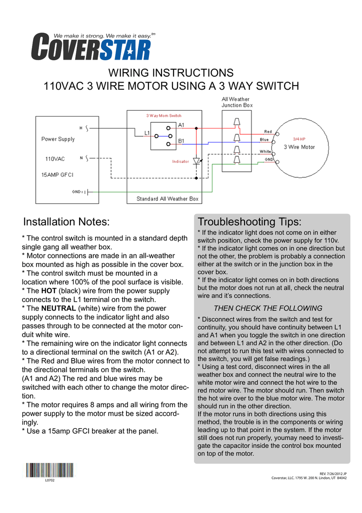
If the mechanism housing has been flooded or any of the electrical connections have been compromised ie. Receptacle must have a weatherproof cover that can be closed when the cord is. POWERTOUCH WIRING Electrical Wiring Diagram A WARNING A Do not attempt to connect or disconnect the control unit or motor harness while supply power is ON.
There are just thr. Make sure the cover sides ARE ALIGNED STRAIGHT to feed directly into the track. It shows the components of the circuit as simplified forms and the power and also signal links in between the gadgets.
The mechanism roughly in the position that they. How To Add a Line to the Pool Bonding Wire HTG - httpbitly2RmVZaXIs My Pool Pump 115V or 230V Blog - httpbitly2RnPdkYHow to Read Pump Motor Labels. 50134 model save t cover ii pool controller user manual installation owners indd pools wiring instructions 110vac 3 wire motor using the touchpad a2463 a2469 troubleshooting tips installatio electric modpools guide remote controllable automatic by high power control system.
They said they could bypass it by wiring in a 120V key switch at 280. Baldor Motor Wiring Diagram baldor 5hp motor wiring diagram baldor brake motor wiring diagram baldor dc motor wiring diagram Every electrical structure is composed of various diverse parts. Wiring Diagram Motor Control System Best Remote Controllable.
A wire connector is provided on this unit to connect a minimum 8 awg. A wire connector is provided on this unit to connect a minimum 8 awg. One motor drives the cover drum which pulls the fabric off the pool and the other motor drives the rope ta ke-up reel that pulls the cover fabric onto the pool.
If not the arrangement will not function as it should be. Electric 34 hp motor electric 34 hp motor Hydraulic 1-12 hp motor POOL COVER HOUSING Conduit with 3 18 AWG Identified Wires for Low Voltage Key Switch Option 1. Stainless Steel Cable Slip Clutch Auto-shutoff CoverLink Control Pad Latching Strap Please read operation instructions for these features.
1 Pool Pump Receptacle Outlet and Wiring Method A. Open the cover and attach a magnet to the. Auto Pool Cover Motor WiringBypassing Limiter.
Automatic Pool Cover Owners Manual This pool cover has been installed with the following features. 84mm solid copper conductor between this unit and the bonding grid and is require by code. Doing so can irreversibly damage controller and cover motor and potentially cause serious injury or death.
A wiring diagram is a streamlined conventional photographic representation of an electric circuit. Connect the electric switch by wiring the neutral wire from the power supply the white wire from the motor and one of the wires from the indicator light together using a wire nut. Safety Pool Cover MECHANISM Step By Step Instructions PageStep.
It is pretty easy. Disconnect all six wires and isolate them from each other. This pump supplies pressurized hydraulic fluid to the drive unit via two hydraulic hoses.
Connect the ground wires from the power supply and the motor together using a wire nut. Bare wires do not operate the system or go near the pool until a qualified electrician has made. Wiring a Pool Pump.
3 WIRE MOTOR 115230VAC GRN WHT BLK GRN RED BLK WHT 115 230VAC HYDRAULIC WIRING SCHEMATIC 3 WIRE MOTOR WIRING SCHEMATIC 7 Attach the sensor over or under cover in a fixed location near webbing so that a magnet placed on the cover will pass within 12 inch of the sensor when attached to the cover. Positioning the roll-up tubemechanism. Try operat-ing the cover again.
8 Step By Step Instructions Position the motor end and non motor end of.
Technical Diagrams American Pool Safety Pool Specialists Inc

Swimming Pool Electrical Wiring Diagram Pool Electrical Pool Filters Swimming Pool Electrical

Pool Cover Switch Wiring Question Electricians

Remote Controllable Automatic Pool Cover By High Power Remote Control System Remote Control Everything
Wiring For Whisperflo Dual Speed Inyopools Com
Servicing Automatic Pool Covers Poolpro

Ac Gearmotor Wiring Help Diy Home Improvement Forum
How To Wire A 2 Speed Pool Pump Intheswim Pool Blog
Electric Cover Installation Modpools Guide
2
2
Infinity Pool Cover Controls Andy S Answers Youtube

50134 Model Save T Cover Ii Pool Cover Controller User Manual Installation Owners Manual Indd Cover Pools
Auto Pool Cover Motor Wiring Bypassing Limiter Ridgid Forum Plumbing Woodworking And Power Tools
Technical Diagrams American Pool Safety Pool Specialists Inc

Automatic Pool Cover Installation Pool Warehouse
3 Wire Motor Wiring Diagram
50134 Model Save T Cover Ii Pool Cover Controller User Manual Installation Owners Manual Indd Cover Pools
2


Posting Komentar untuk "Pool Cover Motor Wiring Diagram"